Computer Controlled Machining
Assignment
Make something "BIG" on a CNC machine.Learning Outcomes
Document the process of design and production to demonstrate correct workflows and identify areas for imporvement if needed.Design Process
For this weeks assignment, I decided to make a pair of cornhole boards. Now if you don't know what cornhole is, watch the video below:Now that you know the game of cornhole, it's time to make the boards. Using SolidWorks I designed the top and side panelling. For this design I decided to go with finger joints. Finger joints are probably the simplist joints to design and cut in CNC machining. If cut right these joints provide suitable strength to the design. As this was my first time designing something for a CNC machine, I utilized the finger joint design. However, if you'd like to learn about more complicated designs for corner joints as well as different joints used in wood joinery please follow this link: CNC Cut Wood Joinery. After designing each seperate part in SolidWorks I created an assembly to make sure everything fit right. The assembly in SolidWorks allows the user to add an array of different parts. With these different parts, "mates" are added to each part as defined by the user so the parts come together. I was going to test out this design on a thicker material, but decided to go for it since I was a little bit behind on this weeks assignment. The slots were designed for a 0.62" thick material, but my final material was 0.5" thick. This meant I needed to go back to each part and make sure the slots and "fingers" were 0.5" thick. It was a fairly easy process to go back and do because I had either patterned and mirrored from one sketch on each part, meaning I usually only needed to alter one sketch on a part.
Once I knew the parts would fit together well, it was time to create the outline drawings for the CNC machine. I first created new drawings in SolidWorks of each part and made sure they were wireframe. I then saved these drawings as .dxf files and imported them into CorelDraw. I then made sure each component was in the layout and spread out enough on the area I had to work with. This whole process is shown in the video below.
If video does not play in current browser, the video can be played here: Week 7 Design Process
Cutting Process
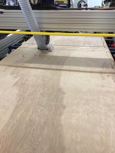
Now that I had the layout for the Shopbot, it was time to cut out my design. I first placed my sheet of plywood on the bed of the Shopbot making sure that the corners all lined up. I then took a drill and drilled out holes at eaach corner to put in screws to secure the piece of plywood to the bed. I also used clamps along the long edge of the plywood to clamp it down and if needed I could remove these if the machine came to close to these. Once the piece of plywood was in place and fastened to the bed I started up Shopbot 3 on the computer. I then did the following:1. Entered Command C3: This command sends the Shopbot to the current "home" position.
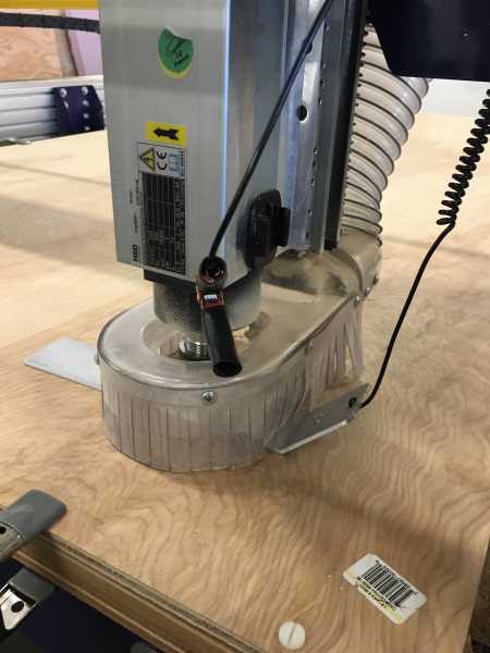
2. Entered Command C2: Used to zero the Z-axis on the Shopbot. Shown in picture below.
3. Moved Spindle: Used the controls on the computer to move the spindle to the corner of material to set new x-axis and y-axis position. Once the spindle was set above the corner of material, I cleared the x-axis and y-axis numbers to set new "home" position.
4. Opened up Aspire: Program used to generate toolpath for Shopbot
5. Imported the .dxf file: Layout that was created in CorelDraw.
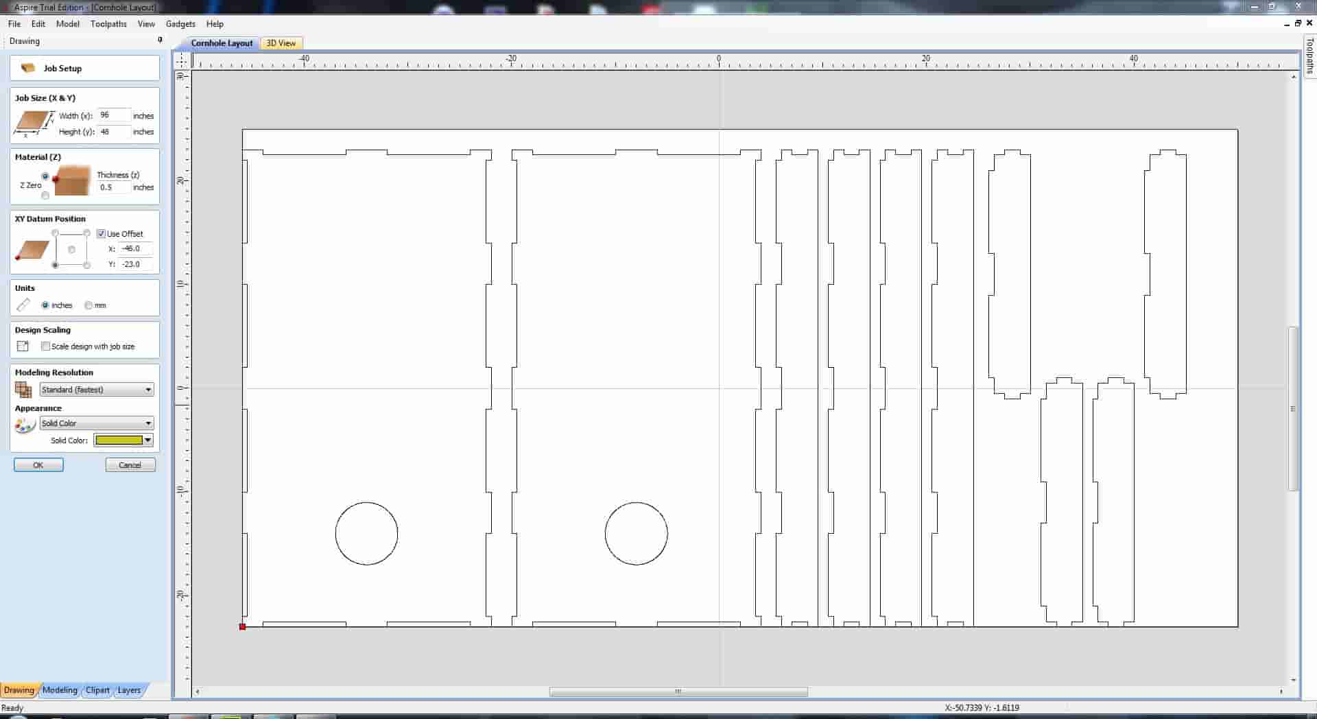
6. Centered Layout: Centered the layout so that it was centered and fit on the material.
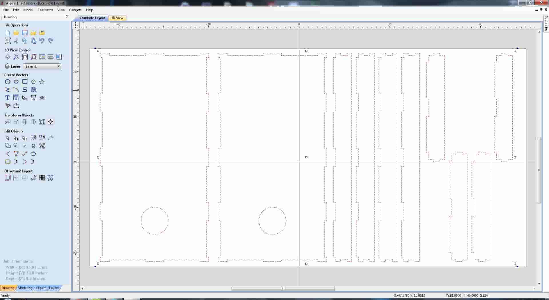
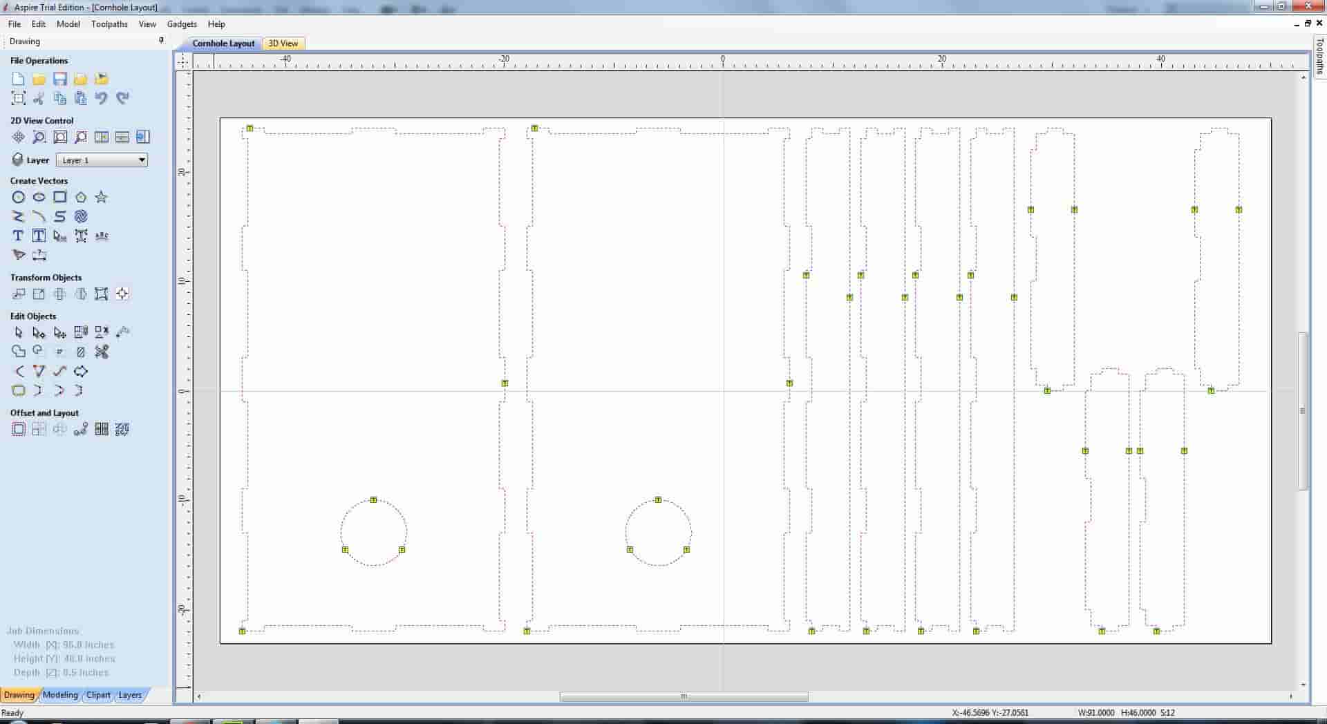
7. Selected All of Design
8. Clicked on Toolpaths
9. Added Tabs to Toolpath: This is where the machine will pick up its tool and not cut through the material leaving a little tab that can be removed once the machine is done.
10. Calculated Toolpath
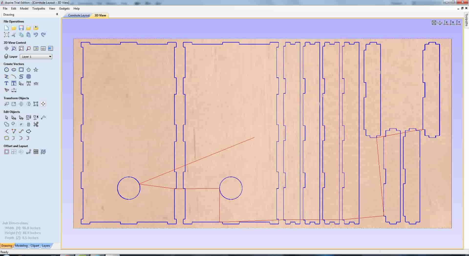
Note: This path shows that the origin is in the center of the board. My mistake was that I had the center selected as the orgin in aspire instead of the bottom left corner.
11. Saved the Toolpath
12. Exported to Shopbot: Used the toolpath that was created in Aspire.
13. Started the Spindle: Manually entered the speed to 18,000rpm.
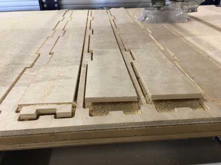
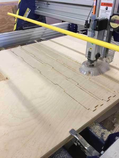
14. Started the cut Tool Used: 1/4 SE 2FL End Mill
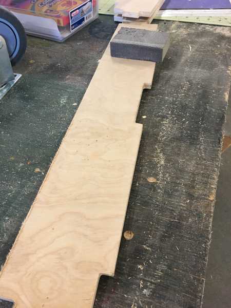
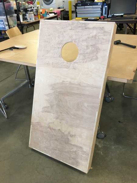
One of the problems I encountered during the cutting process was that there was a bow in the material. As it was cutting out the side panels for the cornhole boards the material bowed up and the spindle ended up cutting through the material that was sticking up as shown in the picture below. I ended up having to put these on a new piece of material and recut them, also shown below.
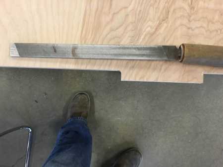
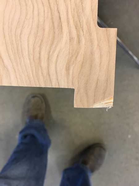
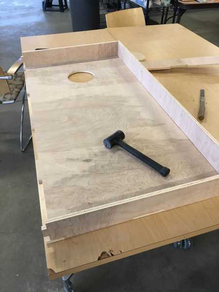
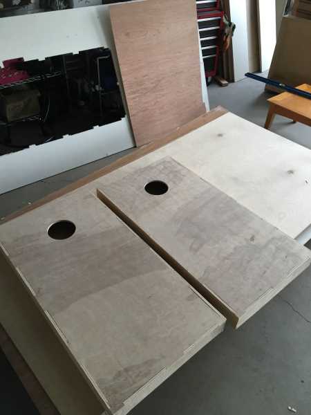
Once all the parts were cut out, I sanded all the parts down to remove the splintered edges. Since my finger joints were rectangle in shape, the corners which the fingers sat were rounded. I took a file to the rounded corners so that the corners came to a sharp edge. This would let it so that all the parts would fit together. Once all the rounded corners were taken care of, I used a rubber mallet and hammered the pieces together. This process and the final products are shown below.
 |
 |
 |
 |
 |
 |
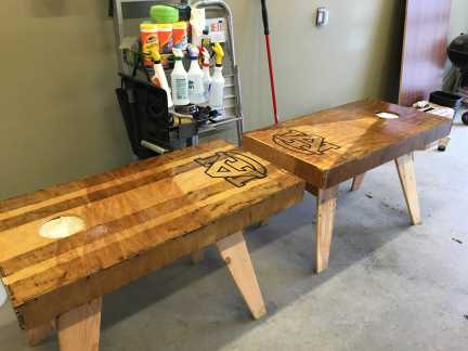
Here is the final product with a custom stain job and vinyl stickers attached:
Project Files
| SolidWorks Parts & Assembly | Drawings and Full Layout |
| Cornhole Top | Cornhole Top DXF |
| Cornhole Side | Cornhole Side DXF |
| Cornhole Side Tops | Cornhole Side Tops DXF |
| Full Assembly | Full Layout DXF |